pure::variants provides specialized editors for each type of model. Each editor can have several pages representing different model visualizations (e.g. tree-based or table-based). Selecting the desired page tab within the editor window changes between these pages.
Since most models are represented as hierarchical tree structures, different model editors share a common set of pages and dialogs.
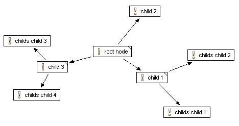
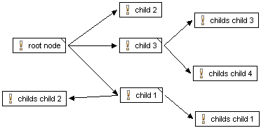
The tree-editing page shows the model in a tree-like fashion (like Windows Explorer). This page allows multiple-selection of elements and supports drag and drop . Tree nodes can also be cut, copied, and pasted using the global keyboard shortcuts (see Section 9.11, “ Keyboard Shortcuts ” ) or via a context menu.
Selection of a tree node causes other views to be updated, for instance the Properties view. Conversely, some views also propagate changes in selection back to the editor (e.g. the outline views).
A context menu enables the expansion or collapse of all children of a node. The level of details shown in the tree can be changed in the "Tree Layout" sub-menu of the context menu. If an attribute is selected in the tree and the context menu is opened, this sub-menu contains the special entry "Hide Attribute: name" is shown. It is used to hide this attribute in the tree view. Hidden attributes can be made visible again with the sub-menu action Table Layout->Change . A dialog is opened which presents a list of all visible attributes and all invisible attributes. This list can be adapted as desired. Additionally the tree layout allows to generally show or hide "Restrictions", "Constraints", "Relations", "Attributes" and "Inherited Attributes". If attributes are set as hidden, the tables mentioned above have no effect. In addition the layouts can be given a name to store them permanently in the eclipse workspace. A named layout can be set as default layout, which can apply for only one tree layout, which then always is used for any newly opened model (see Section 7.4.2, “ Visualization View ” for more information on it).
Double-clicking on a node opens a property dialog for it.
The labels of the elements shown in the tree can be customized on the Variant Management->Visualization preference page.
The table view is available in many views and editors. This view is a tabular representation of the tree nodes. The visible columns and also the position and width of the columns can be customized via a context menu (Table Layout->Change). A layout can be given a name. Named layouts are shown in, and can be restored from, the Visualization view (see Section 7.4.2, “ Visualization View ” ). Named layouts and layout changes for each table are stored permanently in the Eclipse workspace. As for tree layouts a table layout can be set as default. Clicking on a column header sorts that column. The sort direction may be reversed with a second click on the same column header.
Tip
Double clicking on a column header separator adjusts the column width to match the maximal width required to completely show all cells of that column.
Most cells in table views are directly editable. A single-click into a cell selects the row; a second click opens the cell editor for the selected cell. The context menu for a row permits addition of new elements or deletion of the row. A double-click on a row starts a property dialog for the element associated with the row.
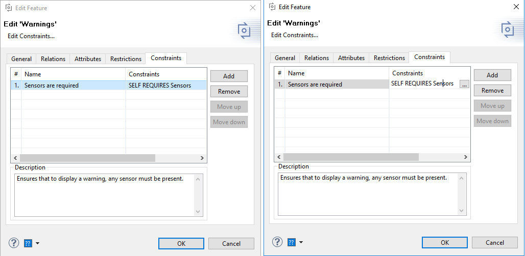
The Constraints page is available in the Feature and Family Model Editor and shows all constraints in the current model. For pure::variant 5 projects constraint can also be added to variant models Constraints can be edited or new created on this page. It also supports to change the element defining a constraint. The defining element is not available for variant models.
Figure 7.3, “Constraints view” shows the Constraints page containing two constraints formulated in pvSCL . The first column in the table of the page contains the name of the constraint. The constraint expression is shown in the second column. In column three the type of the element defining the constraint is shown. The defining element itself is shown in the last column.
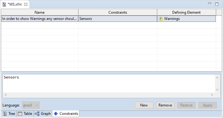
New constraints can be added by pressing button "New". The name of a constraint can be changed by double-clicking into the name field of the constraint and entering the new name in the opened cell editor. Double-clicking into the "Defining Element" column of a constraint opens an element selection dialog allowing the user to change the defining element.
Clicking on a constraint shows the constraint expression in the editor in the bottom half of the page. The kind of editor depends on the language in which the constraint is formulated (see the section called “ Advanced Expression Editor ” for more information about the editor). The language for the constraint expression can be changed by choosing a different language from the "Language" list button.
Changes to constraints are applied using the "Apply" button and discarded using the "Restore" button.
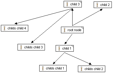
The graph visualization page is primarily intended for the graphical representation and printing of models. Although the usual model editing operations like copy, cut, and paste and the addition, editing, and deletion of model elements also are supported.
Note
The graph visualization is only available if the Graphical Editing Framework (GEF) is installed in the Eclipse running pure::variants. More information about GEF are available on the GEF Home Page .
For nearly all actions on a graph that are explained in the next sections keyboard shortcuts are available listed in Section 9.11, “ Keyboard Shortcuts ” .
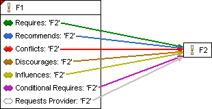
Model elements are represented in the graph as boxes containing the name of the element and an associated icon. Feature model elements are represented as shown in the next figure.

The representation of Family Model elements slightly differs for part and source elements.

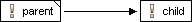
Parent-child relations are visualized by arrows between the parent and child elements.
Other relations are visualized using colored connection lines between the related elements. The color of the connection line depends on the relation and matches the color that is used for this relation on the tree editing page.
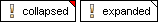
If an element has children a triangle is shown in the upper right-hand corner of the element box. Depending on whether the element is collapsed or expanded a red or white corner is shown.
The layout of the graph can be changed in several ways. Graph elements can be moved, expanded, collapsed, hidden, and automatically aligned. The graph can be zoomed and the layout of the connections between the elements of the graph can be changed.
Two automatic graph layouts are supported, i.e. horizontal aligned and vertical aligned. Choosing "Layout Horizontal" from the context menu of the graph visualization page automatically layouts the elements of the graph from left to right. The elements are layouted from top to bottom choosing "Layout Vertical" from the context menu.
Depending on the complexity of a graph the default positioning of the connection lines between the elements of the graph may not be optimal, e.g. the lines overlap or elements are covered by lines. This may be changed by choosing one of three available docking rules for connection lines from the submenu "Select Node Orientation" of the context menu.
- No Docking Rule
The connection lines point to the center of connected elements. Thus connection lines can appear everywhere around an element.
- Dock Connections on Left or Right
The connection lines are positioned in the middle of the left or right side of connected elements. This is especially useful for horizontally layouted graphs.
- Dock Connections on Top or Bottom
The connection lines are positioned in the middle of the top or bottom side of connected elements. This is especially useful for vertically layouted graphs.
The graph can be zoomed using the "Zoom In" and "Zoom Out" items of the context menu of the graph visualization page.
Several elements can be selected by holding down the SHIFT or STRG key while selecting further elements, or by clicking somewhere in the empty space of the graph visualization page and dragging the mouse over elements. A dashed line appears and all elements that are partially or wholly enclosed in it will be selected.
If an element has children the element can be expanded or collapsed by clicking on the triangle in the upper right-hand corner of the element's box. Another way is to use the "Collapse Element", "Expand Element", and "Expand Subtree" context menu items. In contrast to the "Expand Element" action, "Expand Subtree" expands the whole subtree of an element, not only the direct children.
To hide an element in the graph this element has to be selected and "Hide Element" has to be chosen from the context menu. Attributes, relations, and the connection lines between related elements (relations arrows) also can be hidden by choosing one of the items in the "Show In Graph" submenu of the context menu.
Elements can be moved by clicking on an element and move the mouse while keeping the mouse button pressed. This only works if the element selection tool in the tool bar is selected.

Basic editing operations are available for the graph. The elements shown in the graph can be edited by choosing "Properties" from the context menu of an element. Elements can be copied, cut, pasted, and deleted using the corresponding context menu items.
New elements can be created either by choosing one of the items below the "New" context menu entry or by using the element creation tool provided in the tool bar of the graph visualization page.
The properties dialog for an element contains a General, Relations, Attributes, Restrictions, and Constraints page.
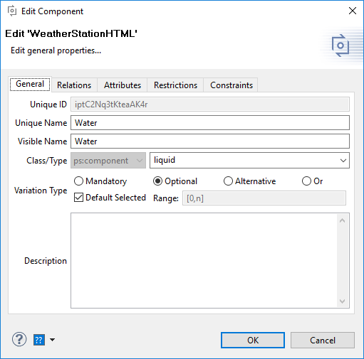
This page configures the general properties of a model element. According to the model type the available element properties differ (see Figure 7.6, “Family Model Element Properties” ).
The following list describes the properties that are always available.
- Unique ID
The unique identifier for the model element. This identifier is generated automatically and cannot be changed. Every Feature Model element has to have a unique identifier.
- Unique Name
The unique name for the model element. The name must not begin with a numeric character and must not contain spaces. The uniqueness of the name is automatically checked against other elements of the same model. The unique name can be used to identify elements instead of their unique identifier. Unique names are required for each feature, but not for other model elements. The Unique name is displayed by default (in brackets if the visible name is also displayed).
- Visible Name
The informal name for the model element. This name is displayed in views by default. This name can be composed of any characters and doesn't have to be unique.
- Class/Type
The class and type of the model element. In feature models elements can only have class ps:feature . Thus the element class for features cannot be changed. Elements in Family Models can have one the following classes: ps:component , ps:part , or ps:source . The root element of a family model always has the class ps:family . The type of a model element is freely selectable.
- Variation Type
The Variation type of a model element. The variation type specifies, which selection group applies to the element. One of "mandatory" , "optional" , "alternative" or "or" can be selected.
- Range
For variation type Or it is possible to specify the number of features / family elements that have to be selected in a valid configuration in terms of a range expression. These range expressions can either be a number, e.g. 2, or an inclusive number range given in square brackets, e.g. [1,3], or a set of number ranges delimited by commas, e.g. [1,3], [5, 8]. The asterisk character * or the letter n may be used to indicate that the upper bound is equal to the number of elements in the Or group.
- Default Selected
This property defines the default selection state of a model element. Default selected elements are selected automatically if the parent element is selected. To deselect this element either the parent has to be deselected or the element itself has to be excluded by the user or the auto resolver. Note, that by default the default selection state is disabled for features and enabled for family elements.
- Description
The description of the model element. For formatted text editing see Section 7.5.1, “ Common Properties Page ” . The description field is also available on the other pages.
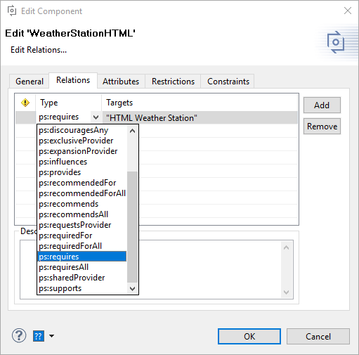
This page allows definition of additional relations between an element and other elements, such as features or components (see Figure 7.7, “Element Relations Page” ). Typical relations between features, such as requires or conflicts, can be expressed using a number of built-in relationship types. The user may also extend the available relationship types. For defining a new custom relation type the name of the new type can be entered into the text filed into the Type column instead of selection on predefined relation from the dropdown list.
More information on element relations can be found in Section 5.2.3, “ Element Relations ” .
Every element may have an unlimited number of associated attributes (name-value pairs).
The attributes page uses a table of trees to visualize the attribute declaration (root row) and optional attribute value definitions (child rows).
Each attribute has an associated Type and may have any number of Value definitions associated with it. The values must be of the specified Type. The number of attribute value definitions is shown in the # column. In the example in Figure 7.8, “Sample attribute definitions for a feature” , the attribute DemoAttribute has two value definitions (1 and 0).
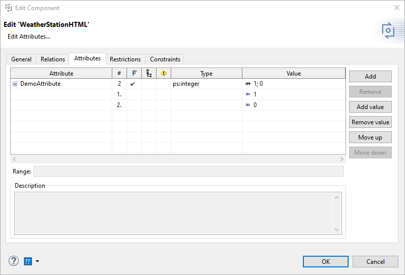
Each attribute of type ps:integer or ps:float may define a range which the attribute values have to fit in. This range can be defined in the "Attribute page" of an element while creating the attribute or the Section 7.4.6, “ Properties View ” after selecting the corresponding attribute. The syntax of the ranges is described in Section 5.2.4, “ Element Attributes ”
Attributes can be
inherited
from parent elements. Checking
the inheritable cell (column icon
 ) in the parent elements Attribute page does this. An
inherited attribute may be overridden in a child element by defining a new
attribute
with the same name as the inherited attribute. The new attribute may
or may not be
inheritable as required.
) in the parent elements Attribute page does this. An
inherited attribute may be overridden in a child element by defining a new
attribute
with the same name as the inherited attribute. The new attribute may
or may not be
inheritable as required.
Attributes can be
fixed
by checking the cell in the
 column. Fixed attributes
are calculated from value definitions in the model in which they are
declared, in
contrast to non-fixed attributes for which the value is specified in a
VDM. Default
values can be (optionally) defined here for non-fixed attributes. These
are used if no
value is specified in the VDM.
column. Fixed attributes
are calculated from value definitions in the model in which they are
declared, in
contrast to non-fixed attributes for which the value is specified in a
VDM. Default
values can be (optionally) defined here for non-fixed attributes. These
are used if no
value is specified in the VDM.
An attribute may have a restricted availability. This is
indicated by a check mark
in the
 column.
Clicking on a cell in this column activates the Restrictions editor. To
restrict the
complete attribute definition use the restriction cell in the attribute
declaration
(root) row. To restrict an attribute value, expand the attribute tree
and click into
the restriction cell of the value. In the appearing dialog
restrictions can either be
entered directly into a cell or by using the Restrictions editor.
Clicking on the
button marked ... which appears in the cell when it is being edited
opens this editor.
See
the section called “
Restrictions Page
”
for detailed information.
column.
Clicking on a cell in this column activates the Restrictions editor. To
restrict the
complete attribute definition use the restriction cell in the attribute
declaration
(root) row. To restrict an attribute value, expand the attribute tree
and click into
the restriction cell of the value. In the appearing dialog
restrictions can either be
entered directly into a cell or by using the Restrictions editor.
Clicking on the
button marked ... which appears in the cell when it is being edited
opens this editor.
See
the section called “
Restrictions Page
”
for detailed information.
During model evaluation, attribute values are calculated in the listed order. The and buttons on the right side of the page can be used to change this order. The first definition with a valid restriction (if any) and a constant, or a valid calculation result, defines the resulting attribute value.
Values can be entered directly into a cell, or by choosing a value from a list (combo box) of predefined values, or by using the Value editor. Clicking on the button marked ..., which appears in the cell when it is being edited, opens this editor. The editor also allows the value definition type to be switched between constant and calculation. The calculation type can use the pvSCL language to provide more complex value definitions. More information on calculating attribute values is given in the section called “ Attribute Value Calculations with pvSCL ” .
The name of an attribute can be inserted directly or chosen from a list of attributes defined for the corresponding element type in the pure::variants type model. When choosing an attribute from the list, the attribute type and the fixed state of the attribute are set automatically.
It is also possible to provide attributes which have a configurable collection of values as data type. Each contained value is available in a variant if the corresponding restriction holds true. To use this feature, square brackets ("[]") for list values or curly brackets ("{}") for set values have to be appended to the data type of the attribute in column Type , e.g. ps:string{} , ps:boolean[] , or ps:integer{} .
The use of attributes is covered further in Section 5.2.4, “ Element Attributes ” .
The Restrictions page defines element restrictions. Any element that can have restrictions can have any number of them. A new restriction can be created using the button. An existing restriction can be removed using . Restrictions are OR combined and evaluated in the given order. The order of the restrictions may be changed using the and buttons on the right side of the page.
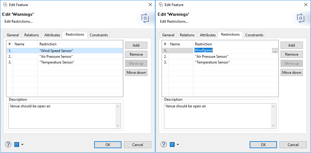
For each restriction a descriptive name can be specified. It has no further meaning other than a short description of what the restriction checks. A restriction can be edited in place using the cell editor (shown in the right side of figure Figure 7.9, “Restrictions page of element properties dialog” ). Note the difference in restriction #1 in the left and right sides of the figure. Unless they are being edited, the element identifiers in restrictions are shown as their respective Visible names (e.g. 'Wind Speed Sensor) when available. When the editor is opened the unique name is shown (e.g. 'WindSpeed'), and no element identifier substitution takes place. The ... button opens an advanced editor that is more suitable for complex restrictions. This editor is described more detailed in the section called “ Advanced Expression Editor ” .
The Constraints page defines model constraints. Any element that can have constraints can have any number of them. A new constraint can be created using the button. An existing constraint can be removed using . The order of constraints may be changed using the and buttons on the right side of the page. This has no effect on whether a constraint is evaluated or not; constraints are always evaluated.
For each constraint a descriptive name can be specified. It has no further meaning other than a short description of what the constraint checks. A constraint can be edited in place using the cell editor (shown in the right side of figure Figure 7.10, “Constraints page of element properties dialog” ). The ... button opens an advanced editor dialog that is more suitable for complex constraints. This editor is described more detailed in the section called “ Advanced Expression Editor ” .
The advanced expression editor is used everywhere in pure::variants where more complex expressions may be inserted. This is for instance when writing more complex restrictions, constraints, or calculations.
Currently it supports the pvSCL language. A special editor is available for the pvSCL language. Figure 7.11, “Advanced pvSCL expression editor” shows the pvSCL editor editing a constraint.
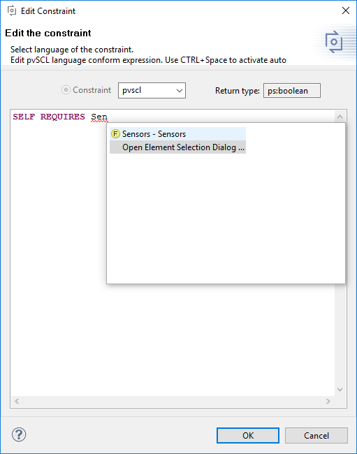
This dialog supports syntax highlighting for pvSCL keywords and auto completion for identifiers. There are two forms of completion. Pressing CTRL+SPACE while typing in an identifier opens a list with matching model elements and pvSCL keywords as shown in the figure. If the user enters "<ModelName>." or "@<ModelId>/" a list with the elements of the model is opened automatically. When pressing CTRL+SPACE the opened list contains all kind of proposals: models, elements and operations, if there is no context information available. Therefore an typing of '"' opens the list with only elements contained. When then one of the elements is selected, the full qualified name of the element is inserted into the code, i.e. "<ModelName>.<ElementName>". There is always a special entry at the end of such a list, "Open Element Selection Dialog...", which opens the Element Selection dialog supporting better element selection. This dialog is described more detailed in the section called “ Element Selection Dialog ” .
The element selection dialog (figure Figure 7.12, “Element selection dialog” ) is used in most cases when a single element or a set of elements has to be selected, e.g. for choosing the relation target elements when inserting a new relation. The left pane lists the potentially available elements, the right pane lists the selected elements. To select additional elements, select them in the left pane and press the button ==> . Multiple selection is also supported. To remove elements from the selection, select them in the right pane and use the button <== .
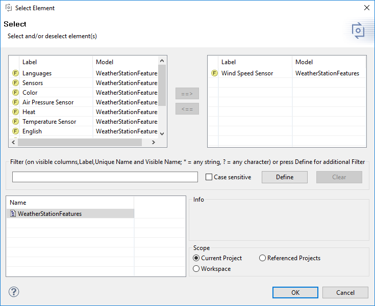
The model selection and filter fields in the lower part of the dialog control the elements that are shown in the left Label field. By default, all elements for all models within the current project are shown. If a filter is selected, then only those elements matching the filter are shown. If one or more models are selected, then only elements of the selected models are visible. If the scope is set to Workspace then all models from the current workspace are listed. The model selection is stored, so for subsequent element selections the previous configuration is used.
Tip
The element information shown in the left and right Label fields is configurable. Use Table Layout->Change... from the context menu to select and arrange the visible columns. See the section called “ Table Editing Page ” for additional information on table views.
Every open Feature Model is shown in a separate Feature Model editor tab in Eclipse. This editor is used to add new features, to change features, or to remove features. Variant configuration is not possible using this editor. Instead, this is done in a variant description model editor (see Section 7.3.4, “ Variant Description Model Editor ” and Section 4.4, “Using Configuration Spaces” for more information).
The default page of a Feature Model Editor is the tree-editing page. The root feature is shown as the root of the tree and child nodes in the tree denote sub-features. The icon associated with a feature shows the relation of that feature to its parent feature (see Table 9.4, “Element variation types and its icons” ).
Some keyboard shortcuts are supported in addition to mouse gestures (see Section 9.11, “ Keyboard Shortcuts ” ).
Whenever a new Feature Model is created, a root feature of the same name is automatically created and associated with the model.
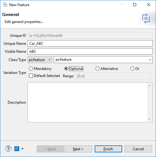
Additional sub-features may be added to an existing feature using the context menu item. This opens the New Feature wizard (see Figure 7.14, “New Feature wizard” ) where the user must enter a unique name for the feature and may enter other information such as a visible name or some feature relations. All feature properties can be changed later using the Property dialog (context menu entry , see the section called “Changing feature properties” ).
A feature may be deleted from the model using the context menu entry Delete. This also deletes all of the feature's child features.
Cut, copy and paste commands are supported to manipulate sub-trees of the model. These commands are available on the Edit menu, the context menu of an element and as keyboard shortcuts (see Section 9.11, “ Keyboard Shortcuts ” ).
Feature properties, other than a feature's Unique Identifier , may be changed using the Property dialog. This dialog is opened by double-clicking the feature or by using the context menu item (see Figure 7.15, “Feature Model Element Properties” ).
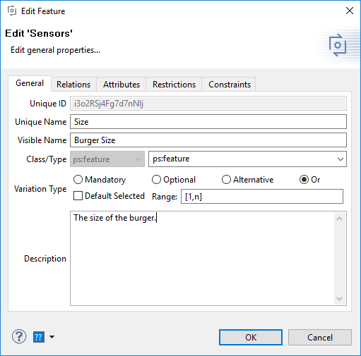
See the section called “ Element Properties Dialog ” for more information about the dialog.
The Family Model Editor shows a tree view of the components, parts,
and source
elements of a solution space. Each element in the tree is shown with an
icon representing
the type of the element (see
Table 9.8, “Predefined part types”
). The
element may additionally be decorated with the restriction sign
if it has associated restriction
rules. For more information on Family Model concepts see
Section 5.4, “
Family Models
”
.
The VDM Editor is used to specify the configuration of an individual product variant. This editor allows the user to make and validate element selections, to set attribute values, and to exclude model elements from the configuration.
In this editor there are two tree views, one showing all feature models in the Configuration Space and another showing all family models in the Configuration Space.
A specific model element can be explicitly included in the configuration by marking the check box next to the element. Additional editing options are available in the context menu. For instance, there are menu entries for deselecting or excluding one or whole sub-trees of elements. It is not supported to make a selection for two elements with the same unique name of models with the same name.
Elements may also be selected automatically, e.g. by the Auto
Resolver enabled by
pressing button
 .
However, the context menu allows the exclusion of an element; this
prevents the Auto
Resolver from selecting the element.
.
However, the context menu allows the exclusion of an element; this
prevents the Auto
Resolver from selecting the element.
Each selected element is shown with an icon indicating how the selection was made. The different types of icons are documented in Table 9.5, “Types of element selections” . If the user selects an element that has already been selected automatically its selection type becomes user selected and only the user can change the selection.
When the
 icon is
shown instead of the selection icon, the selection of the element is
inadvisable since
it will probably cause a conflict.
icon is
shown instead of the selection icon, the selection of the element is
inadvisable since
it will probably cause a conflict.
Since automatically calculated selections may be changed during evaluation by the auto resolver to make the selectgions valid the Variant Description Model editor provides an action to make the current selection explicit. Meaning the current automatic calculated selection can be changed to explicit user selections to prevent the auto resolver from changing them. This is done with the Finalize Configuration from the editors context menu. This action opens a new dialog whioch allows the user to select which selections will be changed to explicit selections.
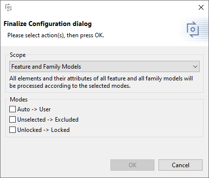
First the scope allows the user to selected wether the feature or family models or both shall be considered. The modes allow the user to select wether auto selections shall be converted into user selection and if unselected elements shall be excluded. Additionally the converted selections can be locked, so the user can not change them by accident.
The Reopen Configuration action reverts the finalization.
In addition to configuring variants in the Variant Description ModelEditor , pure::variants offers the possibility to create Variant Configuration Wizards that guide the user through the configuration process. The Variant Configuration Wizard is available in the Variant Description Model Editor and as part of the Model Viewer in the pure::variants Web Components .
If a configuration space is configured to use a Variant Configuration Wizard Model the Variant Description Model editor shows an additonal editor viewer named Wizard . See Section 6.19, “Customizing the Variant Configuration Process” for detailed information on how to configure the Variant Configuration Wizard.
The wizard is devided into two areas. The left area lists the configurations steps that the wizard provides. The bigger area on the right is the configuration area. It allows the user to make selections and also displays the start and finish page of the wizard.
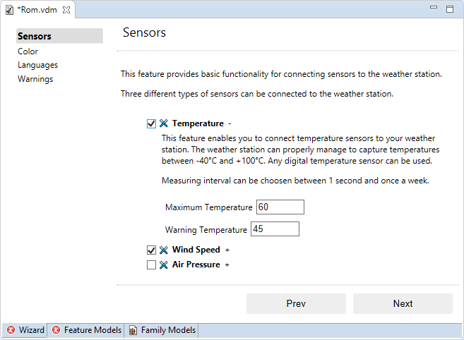
After clicking the Start button, the user is guided through the configuration process step by step. Each configuration step is displayed on a single page in the wizard, and this page lists all the configuration items that are necessary to complete the corresponding configuration step. (See Figure 7.19, “Variant Configuration Wizard Step Page” ) If a configuration item has an associated description, this description is shown below the item. In addition to individual configuration items, a configuration step itself can also have a description. This description is shown at the top of the page.
In this example, shown in Figure 7.19, “Variant Configuration Wizard Step Page” an or group is shown, which means that at least one element has to be selected. Selecting elements may change the content of the step page. Since selecting Temperature requires configuring the values of the attribute Maximum Temperature and Warning Temperature those two attributes automatically become visible on the page.
The buttons Prev and Next allow page navigation. Next is avilable only after all items in the current configuration step have been configured. Using the Prev button resets all configuration decisions that have been made on the current page and navigates back to the previous page.
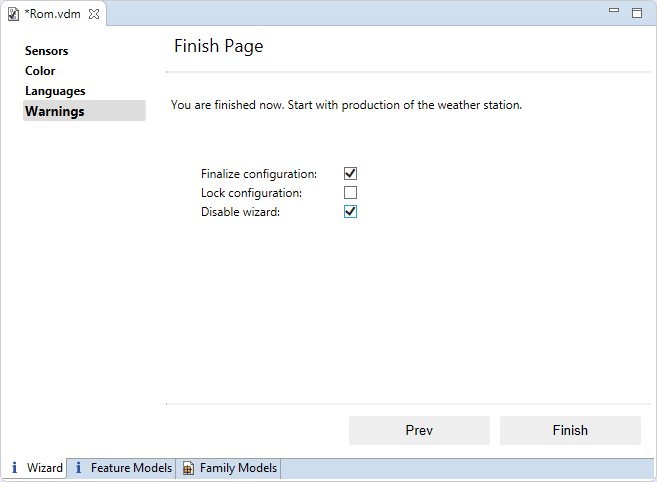
After all configuration steps are done, the finish Page is shown (See Figure 7.20, “Variant Configuration Wizard Finish Page” ). The finish page lists the following options: Finalize configuration automatically converts derived selections and values into user selections and values. The effect of this conversion is that all configuration decisions made in the wizard, even those that were computed by the auto resolver, are treated as if they were made manually by the user. As such, the auto resolver will not change these decisions accidentally if the variant model is reopended later on. The only possibility to revise these configuration choices is through explicit user interaction. Lock configuration locks all user selections so they can not be changed later. Disable wizard disables the wizard for the currently configured Variant Description Model. This means the wizard is not shown, if the Variant Description Model is opened again.
Pressing the Finish button performs the selected actions and saves the Variant Description Model.
The value of non-fixed attributes is specified in the VDM. Therefore, the Variant Description Model Editor allows to change non-fixed attributes. There are three possibilities:
with the Properties view (see Section 7.4.6, “ Properties View ” )
with the Attributes view (see Section 7.4.1, “ Attributes View ” )
with the cell editors of the Variant Description Model Editor itself
Only the first possibility will be explained in detail. The other two possibilities are similar to the first.
First make sure the VDM editor displays attributes (use context menu -> ). Next, double-click on the attribute you would like to specify a value for. A cell editor opens and a text can be entered for the attribute or pressing the button opens the Value editor dialog. The given value will be applied with a click somewhere else in the tree.
Alternatively, values can be added to a non-fixed/editable attribute of a VDM or other models by right-click on it and navigating to New -> Attribute value. This action will provide relevant dialogs to input values. By pressing OK in the dialogs, the value can be stored in the attribute.
For list and set attributes a special dialog appears when editing attribute values in VDMs. The table represents the values and provides possibility to add (using Add value button), edit (by double clicking the table cells), remove (one or multi select) or re-arrange values.
Attributes of grey color mean that there is currently no value set for the attribute and that the default value of the attribute is taken from the associated Feature or Family Model. If no value is specified in VDM for an attribute with default value then a warning will be shown, calling attention to that issue. Attributes with no value in VDM and no default value will produce an error during evaluation.
The outline view of the VDM shows the selected elements with their selection state. You can click on an element to navigate to it in the VDM. This view may be filtered from the views filter icon or context menu.
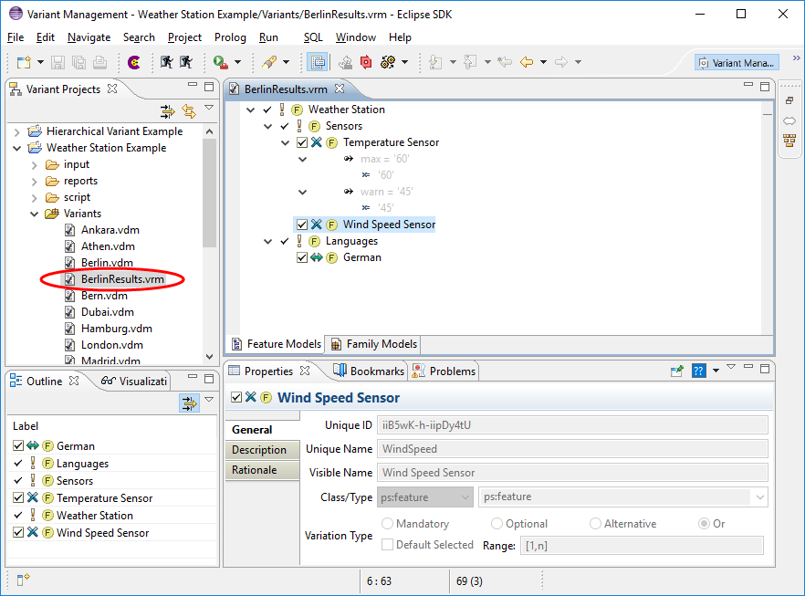
The Variant Result Model Editor (VRM Editor) is used to view a
saved Variant Result
Model. To open a Variant Result Model, double-click on the corresponding
file (suffix
.vrm
) in the Variant Projects View. This opens the
editor in the style of the VDM Editor.
A Variant Result Model can not be changed because it already represents a concrete variant. Thus the shown element selection is read-only.
If a Variant Result Model is located below a Configuration Space folder, transformation of the Variant Result Model is possible. The required information for the transformation is taken from the Configuration Space. If no valid transformation configuration is found, the transformation will be rejected. A warning is shown if the models of the Configuration Space do not conform to the models in the Variant Result Model.
Figure 7.23, “VRM Editor with outline and properties view” shows a sample variant result model.
See Section 5.9.2, “ Variant Result Models ” for more information about Variant Result Models.
The Model Compare Editor is a special editor provided by pure::variants to view and treat differences between pure::variants models. The behaviour of this editor is very similar to that of the Eclipse text compare editor. For general information about the Eclipse compare capabilities please refer to the Eclipse Workbench User Guide . The Task section contains a subsection Comparing resources which explains the compare action in detail. For more information on the use of the pure::variants Model Compare Editor see Section 6.6, “ Comparing Models ” .
The matrix editor gives an overview of feature selections and
attribute values across
the variants in a configuration space. The editor is opened by
double-clicking on the
configuration space icon
 in the
Variant Projects
view (see
Figure 7.24, “Matrix Editor of a Configuration Space”
). The editor may be filtered based on the selection states of
features in the
individual Variant Description models: one filter shows the features that
have not been
selected in any model, one filter shows the features that have been
selected in all
models, and one filter shows the features that have been selected in at
least one model.
The filters are accessed via the context menu for the editor (Show
elements). The general
filtering mechanism can also be used to further specify which features are
visible (also
accessible from the context menu).
in the
Variant Projects
view (see
Figure 7.24, “Matrix Editor of a Configuration Space”
). The editor may be filtered based on the selection states of
features in the
individual Variant Description models: one filter shows the features that
have not been
selected in any model, one filter shows the features that have been
selected in all
models, and one filter shows the features that have been selected in at
least one model.
The filters are accessed via the context menu for the editor (Show
elements). The general
filtering mechanism can also be used to further specify which features are
visible (also
accessible from the context menu).
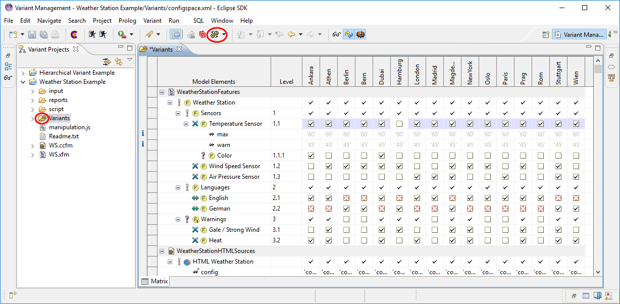
The Matrix Editor allows to change selections and attribute values per VDM. As for the table, the columns of the Matrix Editor can be changed via the same context menu ( Table Layout->Change...) . The first column, which shows the Configuration Space relevant Input Models in the order as they would appear for the VDM Editor, can not be (re)moved. The Input Model Values column, which is visible by default, can be shown but not moved, since its supposed to show the values of attributes as they are defined in the input model and needs those next to it. Additionally the table layout allows the user to define the VDMs visible in the matrix. This selection can be stored in a Matrix Variant Filter . Those filters can be used to open the matrix on the VDMs only matching the filter as well as starting transformation and evaluation on the same filter matching VDMs.
To store the currently opened VDMs in a filter use the Create Matrix Variant Filter action from the context mennu of the Matrix Editor. The second possibility to create such a filter is to select a number of VDMs in the projects view and use the Create Matrix Variant Filter action from the context menu of the project view. A dialog comes up to define a name for the new filter.
In addition the Matrix Editor allows to evaluate the VDMs. This is
done with the
Evaluate Models
button in the editors toolbar, identical to the VDM
Editor. Evaluation capability of the Matrix Editor also includes the
buttons in the
toolbar
Enable automatic checking...
and
Enable auto
resolver...
. If an evaluation is performed, only the currently visible VDMs
are evaluated. The result of the evaluation will be visible in
different ways depending on
the type of the object the cell represents. A Restriction will show
its evaluation state.
A not evaluated Restriction will be shown as
 , whereas a possitively or negatively evaluated Restriction
will show
, whereas a possitively or negatively evaluated Restriction
will show
 , or
, or
 respectively. A Constraint will always show a
 , since it will produce an
error, if the condition is not met. If no value for an attribute can be
calculated, a
, since it will produce an
error, if the condition is not met. If no value for an attribute can be
calculated, a
 is shown in the
corresonding cell to indicate that the attribute has no value at all under the
current
configuration.
is shown in the
corresonding cell to indicate that the attribute has no value at all under the
current
configuration.
Lastly it is even possible to perform transformation of the visible VDMs. Use the Transform all models button to perform transformation. See Section 5.9, “ Variant Transformation ” for detailed information.
The Matrix shown in the editor can be exported to various output formats using the Export Matrix... action from the context menu. The dialog, which opens, allows the user to chose the output format and location for the export.
Note
The Export Matrix... action is available only, if the pure::variants - Connector for Reporting with BIRT is installed.
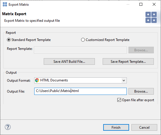
The action export the visible content of the matrix editor, it does even take the expansion state of a element into acount. Meaning collapsed elements and attributes will not be visible in the export result. As well as filtered elements and varaints not opened in the editor.
In the dialog a custom report template can be selected. As a starting point we recommend to use the stadard report template, which can be saved with the Save Report Template.... After customizing the report template, it can be used for future matrix exports.
Note
The template contains a table, which is named "Matrix". This table is the entry point for the matrix exporter. The table can be modified, but there has to be a variant column, which defines the the layout for the columns inserted by the exporter. Which column is the variant column is defined with a user property on the table. Name of the property is "VariantColumn", type is integer. The value is the index of the variant column. The index is 0 based, so third column has index 2. This column is replaced by the exporter with the necessary variant columns.
The Save ANT Build File... button generates an ANT Build file, which can be used to run the report generation in head less mode automatically by any build system. See Section 6.14, “External Build Support (Ant Tasks)”
The generated build file uses the same tree and table layout like currently configured in the confguration space editor, including model item visibility and expansion state for the shown model data. Elements not visible due to an applied filter will not be visible in the report if you run the generated ANT build file.